Product classification

Mobile: +8618624918289
E-mail: 290004946@qq.com
Address: Xingyang Gaoshan Town Valve Industrial Park
Pneumatic Soft Sealing Butterfly Valve
The D671F-16Q pneumatic fluorine-lined butterfly valve features a central structure composed of the valve body, an inner lining layer (PTFE or rubber), and a valve shaft (stainless steel valve plate or chrome-plated steel valve plate).
Pneumatic Soft Sealing Butterfly Valve
Product Overview
The pneumatic fluorine-lined butterfly valve features a centerline structure, consisting of a valve body, an inner lining layer (PTFE or rubber), and a valve plate (stainless steel or chrome-plated steel), along with a valve shaft. Its streamlined design approximates a straight line for medium flow, offering good regulation performance. The sealing structure is a centerline type seal, ensuring reliable sealing performance with bi-directional zero leakage, and it can be installed in any position. It is widely applicable to gases, turbid liquids, concentrated slurries, powders, and suspended particles.
Product Features
1. The pneumatic butterfly valve has a small operating torque and opens and closes quickly. It uses compressed air as power, with mechanical transmission of the valve rod through a piston rack and gear, allowing the valve plate to rotate from 0 to 90° with the output torque for quick opening and closing actions. It has a simple structure, small size, light weight, low flow resistance, and high flow coefficient, with good sealing performance. It has a wide adjustment range and serves as the actuator in automated control systems.
2. It uses an electric-pneumatic valve positioner, powered by electrical signals and compressed air, receiving a control system input of 0-10mADC or 4-20mADC current signals. The regulator converts the compressed air into a pressure signal for input and output, changing the rotation angle of the valve plate (0-90° at any angle), providing good control for regulating flow and other parameters.
3. It employs an electromagnetic directional valve and a valve position feedback device, powered by AC220V or DC24V, using compressed air to achieve rapid two-position cut-off control of fluid media.
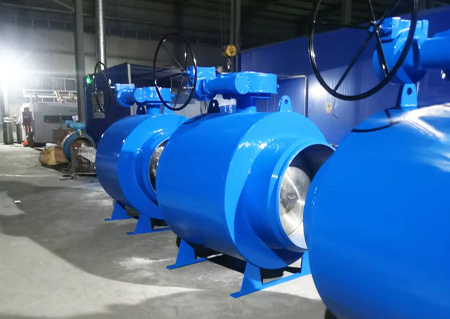
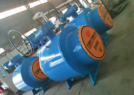
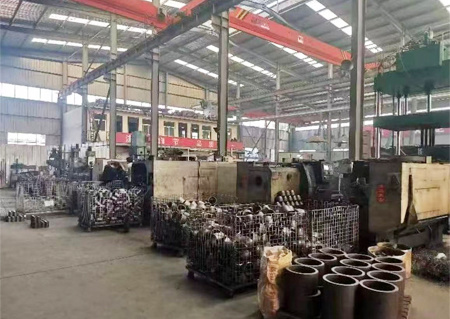
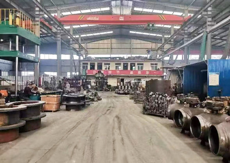
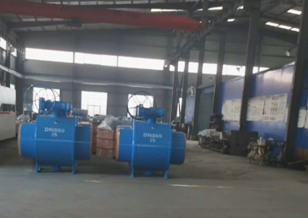
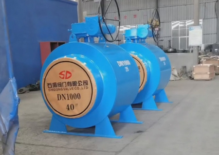
Plant
Application areas

oil and gas

Chemical industry

Food and beverage

Steam industry

Shipbuilding and Mining

Other industries
Honor

FAQ

1. Before installation, check whether the specifications, pressure, temperature, and corrosion resistance of the butterfly valve meet the usage requirements. Inspect all parts for damage or looseness.
2. This butterfly valve can be installed on pipes at any angle, preferably in a closed position; when welding the pipe flange, cover the valve sealing surface with a plate to prevent particles and debris from damaging the sealing surface. After welding, remove the valve, clean the sealing surface and the inner cavity of the pipe, and then install and secure the valve.
3. During installation, pay attention to the pressure direction when the valve is in the closed state.
4. Before installation, thoroughly clean the sealing surfaces (both ends, butterfly plate sealing surface, and valve seat sealing surface) to remove dust and dirt.
5. Before installation, perform a trial operation of the butterfly valve; it should open and close smoothly, and the open/close position should match the pointer position. Manual operation: clockwise to close, counterclockwise to open; do not apply additional force once the pointer is in position.
7. When conducting pressure tests on the valve, do not use a single flange for installation and pressure testing; double flanges must be used. When tightening bolts, do so in a symmetrical and alternating manner; do not tighten them sequentially. 9. The limit bolts have been adjusted before leaving the factory and should not be easily adjusted. If the drive device is electric or pneumatic, please read the accompanying drive device manual.
10. If the valve opens and closes abnormally, investigate the cause for repair and elimination; do not use force to operate the valve, as this may cause damage. 11. If the valve malfunction cannot be resolved, please notify our company for product installation, usage, and after-sales service.

If there are no other special requirements for the valve, it can be ordered according to the valve's number. This requires the user to understand the valve number description when ordering the product. Although this may be difficult for the user, selecting the appropriate number based on the parameters of the product they need can ensure that the provided valve fully meets the user's requirements.

1. When storing, the valve passage at both ends must be blocked with cover plates. It should be stored indoors in a dry and ventilated environment, and should be regularly checked and cleaned of dirt. Anti-rust oil should be applied to exposed machined surfaces to prevent rust.
2. Valves must be stored in a dry room and should not be placed outside to avoid damage.
3. Before transportation, valves must be tested and debugged according to the requirements of the contract or standard requirements to prevent user misoperation. For pneumatic or electric ball valves, the power source requirements for the corresponding devices must be listed according to the instructions of the pneumatic or electric device. If the user needs testing and inspection, it must be conducted according to standard requirements to prevent the product from failing to meet its performance due to incorrect testing methods. After pressure testing, any accumulated water inside the valve must be cleaned out before storage.
4. When installing the valve, the cover plates at both ends of the valve must be removed. For valves connected by welding, protective measures must be taken during the welding installation process to prevent adverse effects on the valve due to high temperatures. 5. For valves with a specific installation direction, directional arrows must be marked on the valve body to prevent incorrect installation.

1. Manual valve: When the handle is in a parallel position to the pipeline, the valve is in the open position; when it is at 90 degrees, the valve is in the closed position. Turning the handle clockwise closes the valve, while turning it counterclockwise opens the valve.
2. Worm gear driven valve: Identify using the indicator device installed on the upper part of the valve; turning the handle clockwise closes the valve, while turning it counterclockwise opens the valve. 3. Valves operated by pneumatic, electric, gas-liquid linkage, or hydraulic linkage: Operate according to the relevant actuator manual.
Key words:
Pneumatic Soft Sealing Butterfly Valve
Free Quote
Note: If you have any suggestions, please leave a message or send an email to us, and we will reply to you within 1 working day after receiving the message email.
Related Products


